How to integrate a Duo 6020 kiosk into a furniture?
1. Kiosk Shipping and Installation
The kiosks will be shipped directly to the hotel.
Please organize the necessary hotel resources to ensure that the kiosks are stored in a safe, secure area until the Ariane technicians arrive on-site.
Typically, it is the client’s responsibility to arrange interface testing with third parties during the kiosk installation.
Ariane will supply the client with some suggested dates for the required interface testing.
A general guideline for third-party testing is:
- PMS: 3 days (1-day set-up, 1 day CI testing, 1 day CO testing).
- Payment & Key card system: 1 day each.

⚠️ It is the client’s responsibility to make sure third parties such as PMS, Payment, and Key card system providers receive confirmation |
2. INSTALLATION & CABLING REQUIREMENTS
a. Power supply
Each kiosk requires a 240VAC main supply, and a 30mA, 250VA consumption circuit breaker.
The supply cable should be terminated with an IEC C13 (female) connector, and of sufficient length.
b. Cabinet weight
It should be noted that a fully loaded drawer can weigh UP TO 50Kg. the drawer opens and closes. Please take this into consideration when commissioning the installation.
c. Networking
Each kiosk should be supplied with an RJ45 cable (RJ45 jack + drop cable), connected to the hotel LAN (with access to PMS, key system, and the Internet).
d. Positioning recommendation
The kiosk should not face the sun.
e. Environmental specifications
Temperature -10° / +40°
Humidity <80%
f. Cabinet opening method
An appropriate method needs to be used to open the kiosk drawer. One suggestion by Ariane is to integrate a lock (refer to VIII.)
g. Materials
Take close attention to the dimension provided below, and make sure that the material used is one that can easily be worked on onsite (glass or stone are not recommended).
The hotel is responsible for commissioning the furniture and making sure that its provider will be onsite to assist with any adjustments.
3. HARDWARE PRESENTATION
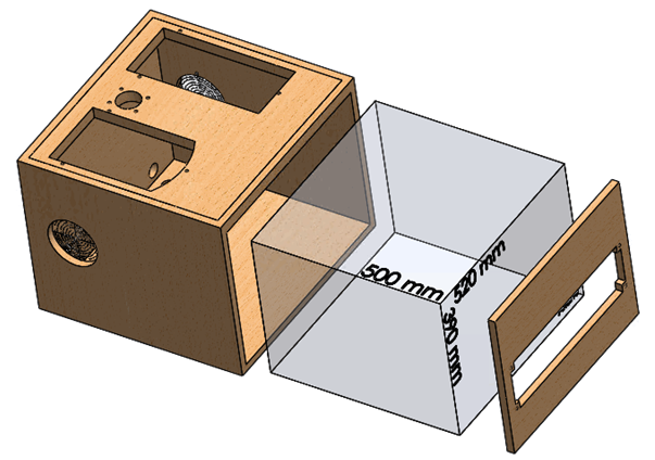
3. INSTALLATION DIMENSIONS (ALL IN MILLIMETERS)
The measurements below represent the minimum required for installation.
The cabinet dimensions can be increased.
Ariane recommends a 3 mm gap on all sides for airflow.
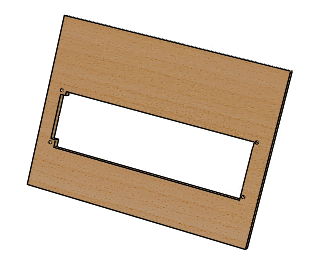
⚠️ Please note that the front panel should fit inside the housing. |
The maximum thickness of the countertop is 30mm.
If exceeded some items cannot be properly fixed!


a. Cutting the front fascia of the furniture
• It is necessary to cut the front fascia of the furniture.
• The view below is from the interior of the kiosk looking out.
• Point A represents the front of your furniture after it has been cut by your carpenter:


b. Cabling and ventilation system
• Points A denotes locations for entry points for cabling.
• Points B denotes the possible locations of the ventilation fan – only 1 is required:

5. OPTIONAL DEVICES
⚠️ Please verify with the hotel and the Ariane Project manager, which of the following devices are actually going to be installed at the hotel. |
If any of those items are not being installed the related holes must NOT be made into the furniture.
a. Integration of a pin pad device (OPTIONAL)
The pin pad must be positioned on the right-hand side of the tabletop.
This equipment is optional.
b. Scanner positioning (OPTIONAL)
The scanner must be positioned on the left-hand side of the tabletop.
This equipment is optional.
c. On pole Payment System
On-pole payment systems are usually installed on site, as the hardware will change based on the provider selected by the hotel.
Make sure that the carpenter will be available onsite to assist with the Ariane team.


6. INTEGRATION OF ALL DEVICES
a. Screen positioning
There is at least the screen integrated. For the other items check with the client and Ariane PM.
b. Global view of the finalized product:


7. CABLE SUPPORT POSITIONING
The cabling support must be aligned with the edge of the top plate, and the thickness of the door should be taken into account.
Please see Annex 5 to see the exact position of those blind holes.

8. CABINET LOCK
You have to install a lock for both safety and security purposes.

9. TECHNICAL DRAWINGS
a. Annex 1: desk cuttings for accessories (optional)
b. Annex 2: Front Door Technical Drawing (mandatory)
c. Annex 3: Cable Holes (mandatory)
d. Annex 4: Fan Hole (mandatory)
e. Annex 5: 2 blind holes (mandatory)
10. INTEGRATION PROCEDURE
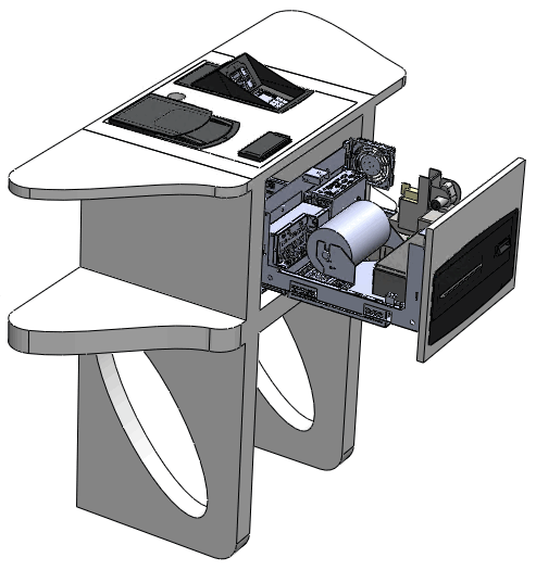
After opening the package, disassemble the scanner, payment, and signature capture options.
The options are fixed on the plate by white knobs underneath.
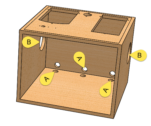
Remove the 4 screws securing the cover (B), and discard the cover (B).
Disassemble and discard the 2 right and left (A) fasteners designed to hold the tray movable during transport.
Move the tray forward (A)
Remove the 2 lower chase support brackets (B)
Push the tray back into place. (C)
Unscrew the 2X3 screws left and right to detach the fixed chassis from the moving plate.
After disassembling the chassis from the tray, remove the moving plate.
Aim the fixed plate at the 6 locations provided using the screws corresponding to the material of the piece of furniture.
Drill one of the 3 slots to pass the power and Ethernet cables.
Replace the movable tray on the fixed chassis.
Reattach the moving plate to the fixed plate with the 6 screws removed previously.
Also, reattach the low chase support.
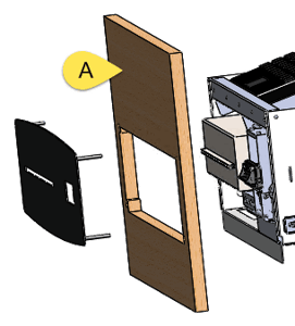
Fit the front door.
Attach the metal front of the terminal to the cabinet door.
Fit the electronic module on the top plate (If present).
Mount the scanner module on the upper platen (If present).
Mount the display bracket on the top plate (If present).
Attach the top chase to the top of the cabinet.